As part of a larger project, I needed a circuit to blink an LED. It’s a simple task, and there are plenty of existing designs. But having almost no experience with circuit design, I wanted to make my own. Further, I wanted to make it with basic components — no ICs. An integrated circuit, like a 555, would take the fun out of it!
As is the case with most oscillators of this sort, the charge/discharge cycle of a capacitor acts as a switch to turn the LED on and off. I sketched out a few ideas, and eventually arrived at this:
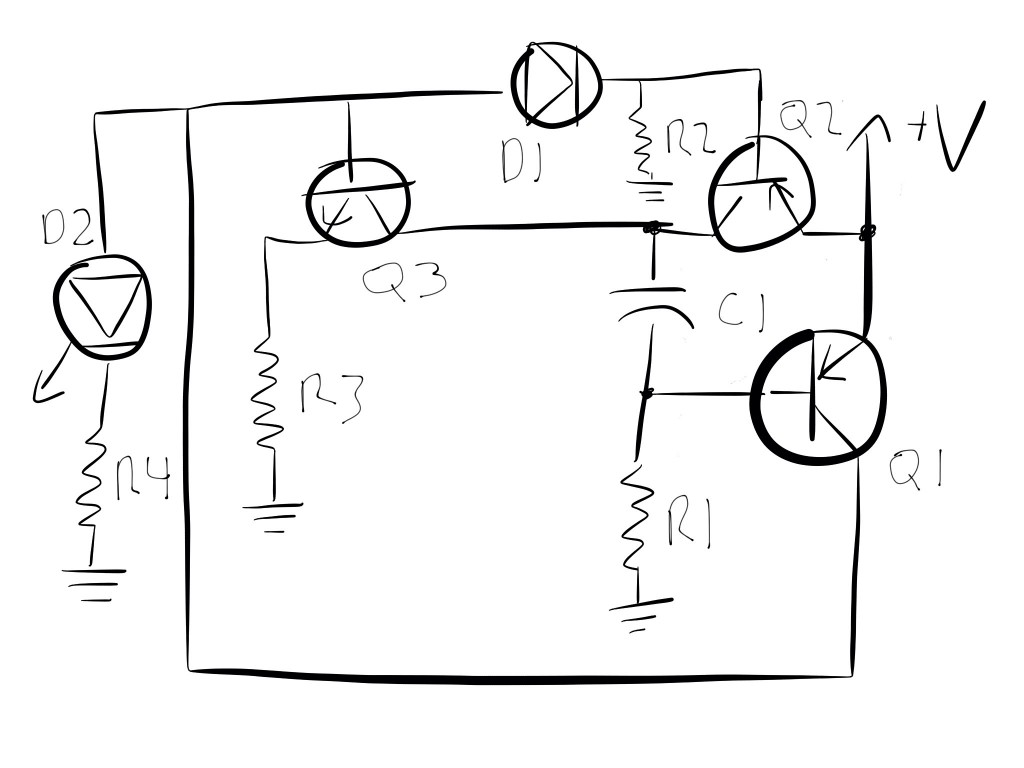
The blinking happens because the circuit oscillates between several states:
- Current goes through PNP transistor Q2 to the anode side of capacitor C1. As C1 charges, the cathode side drains through resistor R1 to ground. In doing so, it also puts “pressure” on the base of PNP transistor Q1, preventing current from flowing through it.
- After C1 is fully charged, its cathode side will no longer be draining, so there will be nothing preventing flow from the base of Q1 through R1 to ground. At that point, Q1 will start to conduct to the big loop, which will cause three things to happen.
- Current will flow to the base of NPN transistor Q3, which will allow C1 to slowly discharge through resistor R3. Also, once Q3 is conducting, the drain on the base of Q1 will increase as current flows to the cathode side of C1.
- Current will flow through diode D1, to put “pressure” on the base of Q2, thereby preventing further charging of C1 from the voltage source.
- Current will flow through light emitting diode D2, causing it to light up.
- Once C1 is fully drained, the base of Q1 will only drain through R1. If R1 has a high enough value, the output of the collector of Q1 will fall below the threshold to block the base of Q2. When that happens, current will once again flow through Q2, C1 will start charging again, Q1 will stop conducting, the LED will turn off, and we return to step 1.
So that was my theory. My next step was to build it, and figure out the right values for all the components. I breadboarded it like this:

Voltage: +5
Q1: (PNP) 9015
Q2: (PNP) 9015
Q3: (NPN) PN2222
R1: 10KΩ
R2: 10KΩ
R3: 680Ω
R4: 68Ω
C1: 470µF
D1: 1N4148
D2: Blue, 3.7V, 20mA
That resulted in a flash rate of 1.3Hz. The blinking speed can be adjusted by changing the capacitor and/or changing the values of R1 and R2. I swapped C1 for a 22µF cap, and the flash rate increased dramatically, perhaps to something between 20 and 30Hz. So I swapped R1 and R2 for 100KΩ, and the flash rate returned to something around 1.6Hz. Ideally, the capacitor should be very small, since it is essentially charging, then dumping its charge in every cycle. I’d like to try to use a much smaller capacitor (with larger R1 and R2 values) to see if I can maintain enough current in that part of the circuit to control the functioning of the transistors. I used a blue, 3.7V LED on a 5V circuit. The LED can be changed, as long as R4 is changed as well to ensure the proper current for the LED’s voltage.
It’s not the simplest circuit of this sort, and I’m sure that I’ve screwed up at least part of the analysis. But as someone who only knows as much about circuit design as he could find on the internet, and a couple of books (namely, Getting Started in Electronics by Forrest Mims, and Starting Electronics
by Keith Brindley), I was fairly pleased with myself for making this work.