In my early 20s, I made what, at that point, was the biggest purchase of my life: my little, green Volkswagen. In both a literal and figurative way, it carried me through some formative years. After 11 years, when repair bills were starting to exceed the value of the car, it finally became time to retire The Green Machine. (It wasn’t an easy decision, but I got a very large estimate to weld out a bad catalytic converter, and weld in a new one that would be necessary to get the car to pass its emissions inspection.) In its place, I wanted something that would handle snowy mountains a bit better — that meant four-wheel drive — and something that I could pay for in cash without totally draining the kitty. I ended up with an 11 year old Jeep Wrangler.
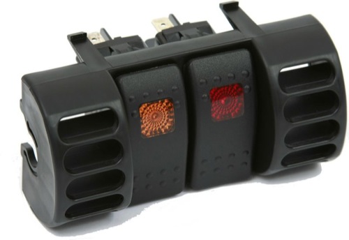
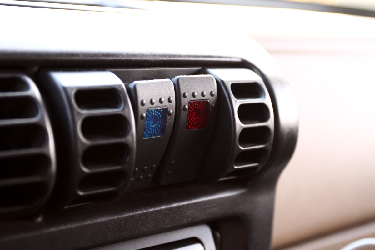
The Jeep has several drawbacks over the Volkswagen. It’s loud. It’s a rough ride. Despite seeming to be quite a bit larger, it doesn’t have much carry capacity at all — packing the car for any long trip becomes an exercise in applied geometry and spacial relations. However, it does have one big advantage: it is user serviceable. It’s a great car for modification and personalization. All cars should be so modular. When a side mirror recently broke, my only problem was deciding what kind of mirror I wanted to replace it with. I browsed through the options on Quadratec, picked a set, they arrived two days later, and it took me 20 minutes to replace both mirrors. When I decided that the stock headlights were too dim, I bought new enclosures for a different bulb type, and swapped the old for the new. Busted radiator? Got a new one at the local auto parts store, and swapped it out. Want seat heaters? Add a fuse block, and wire them to switches on the dashboard. (I’m sure I’ll post more about that one later.)
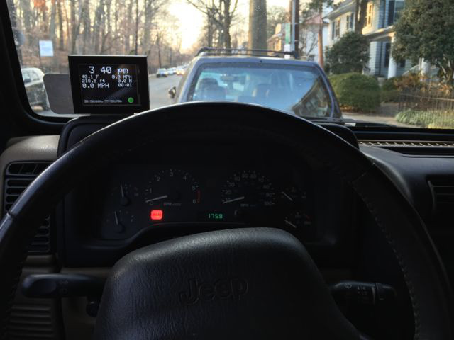
Since I’ve been driving the Jeep, one feature of the VW I have longed for is the little computer that would tell me the temperature outside, how long I have been driving, and my average speed. Maybe I care too much for stats, but I liked to know, eg, This trip was 19 miles, it took 26 minutes, and it is 68° F outside. The Jeep doesn’t even have a clock on the dashboard. No, to be able to see the time, I need to leave the radio (also an aftermarket replacement) on the clock display.
I finally took up the challenge to put together something that would give me the information I so yearned for. I decided to use an Arduino as the microcontroller for the project. I went to my other favorite site, Adafruit, and ordered most of the parts I’d need, such as a digital temperature sensor, a GPS shield, and a touchscreen display. When the parts arrived, it was time to get soldering.
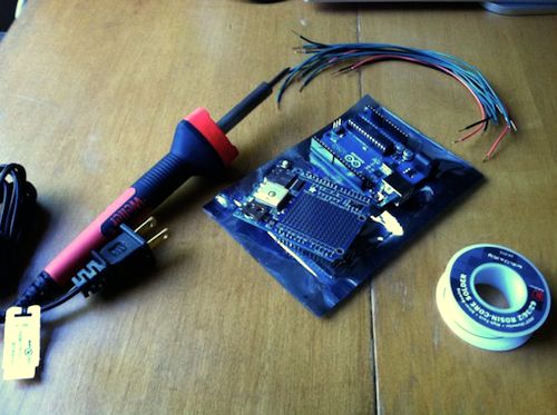
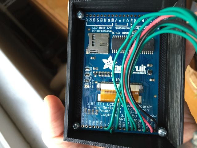
I had to solder the header pins to the GPS shield, and a set of wires to both the GPS shield and the touchscreen in order to connect them to each other. I didn’t want to connect them directly. The plan was to set it up so the microcontroller/GPS unit would be hidden under the dashboard. The display would be affixed to the top of the dashboard. The temperature sensor would be mounted to the front of a front wheel well, and wires would be run back through the engine compartment, and through a small hole I had drilled in the firewall. But before I could do all of that, I wanted to make sure the basic unit worked. Once I figured out how to interface with the temperature sensor, the touchscreen, and the GPS, it wasn’t particularly challenging to write code to pull data from the sensors, and spit the information to the display. I connected the display to the microcontroller/GPS unit through a breadboard, and plugged a 9V battery into it. It was a self-contained unit that I could plop on top of the dashboard.
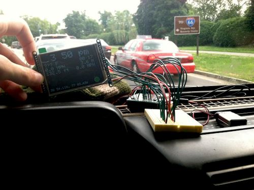
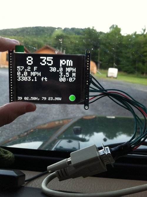
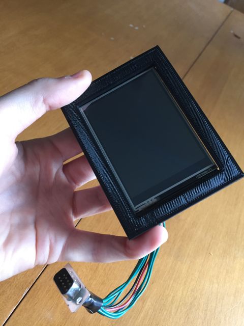
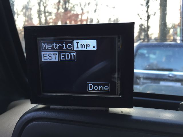
I’m holding the display, which is connected (through the breadboard) to the GPS shield which is plugged in to the Arduino, which is powered by a 9V battery. The display shows the time of day at the top. On the left is the outside temperature (“??? F” since it is not currently connected to the temp sensor), current speed, and altitude above sea level. On the right is current trip information: time, distance, and average speed (“0.0 MPH” because of a bug in my code at that time). At the bottom is the latitude and longitude, and a green dot, indicating that the GPS has a fix.
Once I was generally satisfied with how the device was working, I needed to replace the breadboard with a more convenient connection. I needed to connect nine wires, so I started digging around for a standard RS232 serial cable with a DB9 connector on both ends. Fortunately, I keep around all sorts of old cable that will probably never be useful again. After digging around the box, I found a cable with DB9 connectors. I tested all the pins to make sure that I had a serial cable — where there is a one-to-one connection between pins on each end — and not a null modem cable — where a pin on one end might be connected to multiple pins on the other end. I was in luck; the cable would work. I picked up some solderable DB9 connectors from Radio Shack, and put one end on the display, and the other end on the microcontroller.
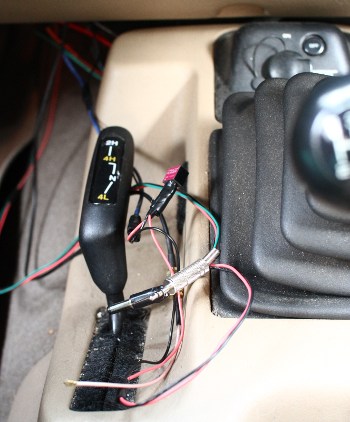
For the temperature sensor, I needed to be able to plug in three wires. I like the simplicity of a standard 1/8″ stereo jack, so I soldered a female end to the wires on the microcontroller, and a male end to the wires from the temperature sensor. So that’s an easy-peasy-parcheesi connection! The only trouble I had with the temperature sensor was joining the wires that ran through the engine compartment. The sensor itself is wrapped in a waterproof casing, and is connected to a 1 meter wire. But that wasn’t long enough to make it to the cabin. Joining longer wires to complete the run was not a problem, but securing them from the elements was a concern. So I picked up some dual-layer heat-shrink. Standard heat-shrink will shrink tightly around a join, but it’s still possible that moisture could get in. Dual-layer heat-shrink has an internal layer of adhesive that melts at a temperature lower than the application temperature. The adhesive fills in the gaps, and creates a waterproof layer — it’s preferable to standard heat-shrink for outdoor applications. So I made the joins, heat-shrunk each of the three individual wires, and tested it. Everything worked fine. I added one more layer of heat-shrink around all three wires, and tested again. The sensor no longer worked. I suspect that I over-heated the wires. Rather than using a proper heat gun, I was just waving a lighter under the heat-shrink. I think I was over zealous in my attempts at shrinkage, and I somehow ruined the connections or wires with too much heat. I had to cut out the connection, pull the remaining wires closer together, and start over. Eventually, I got it right.
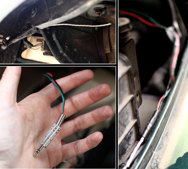
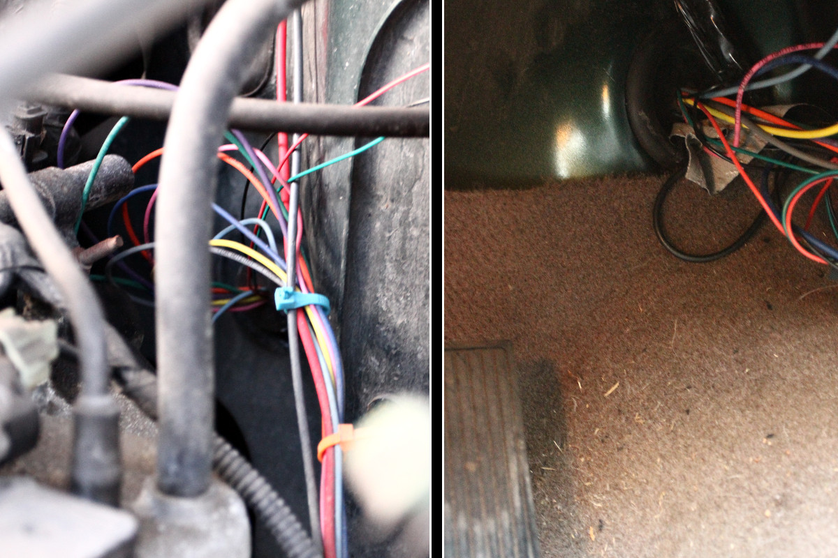
Clockwise from top left: 1) Under the front, drive-side wheel well. The white wire is connected to the temperature sensor. The sensor itself is on the left, wrapped in black Gorilla Tape, to add extra insulation against the elements. 2) Under the hood, the white temperature sensor wire comes from the bottom left up to the point where it is joined (with a length of black heat-shrink) to red, black, and green wires that run to the back of the engine compartment and through the firewall. 3) The wires from the temperature sensor terminate at a 1/8″ stereo plug.
For the GPS, I needed an external antenna, as the GPS chip would eventually be placed under the dash, where it would have a hard time finding a signal. I got an external, active antenna that I could place someplace where it would have good line-of-sight to the satellites. I found that the best location was on top of the dashboard. That made it easy to run the wire behind the dashboard, down to where the microcontroller would eventually be living. The antenna wire ends in an SMA connection (which is a small coax-type connection), so I us an SMA to uFL adapter to connect it to the uFL connector on the GPS shield.
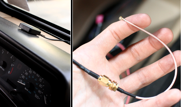
The antenna is mounted on the dashboard. The wire runs behind the dashboard, and terminates in an SMA connector, which is connected to a uFL adapter.
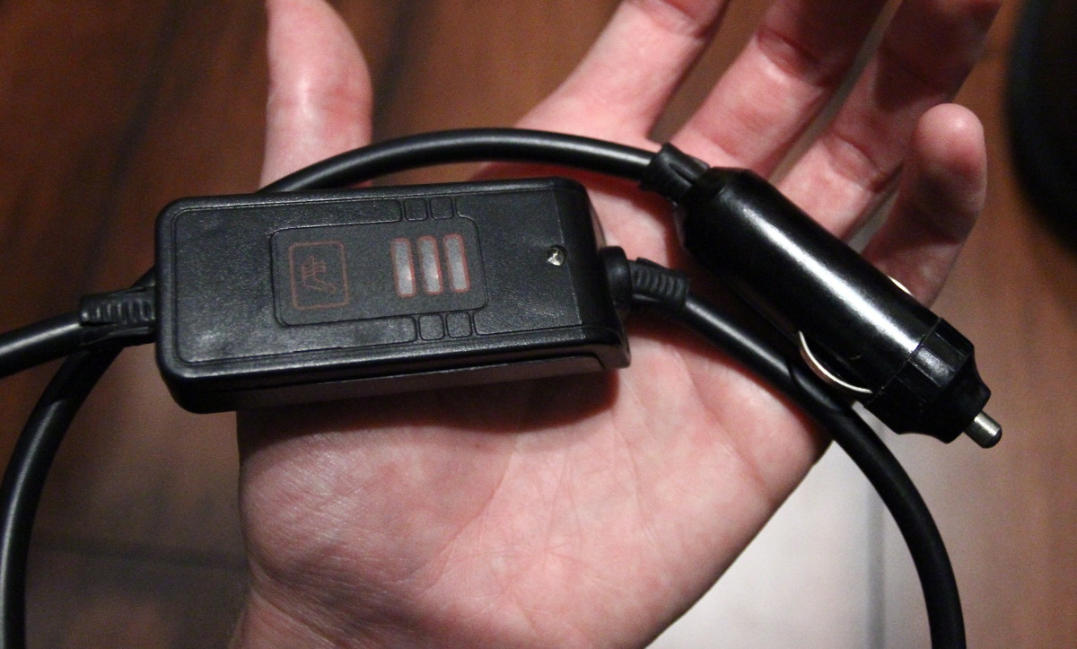
The final piece of the puzzle was power. Fortunately, for other purposes, I had previously installed an extra fuse box in the Jeep, and I had a few spare switched (ie, on when the car is on; off when the car is off) leads in the cabin. I connected one to a 2.1mm power connector, and that was all I needed to do to power the microcontroller. However, when I took the whole contraption for a ride, I noticed that the Arduino ran very hot. The car provides a fairly dirty 12-14 volts, with possible spikes that could get to 18 or 20 volts. Based on the Arduino specs, the on-board voltage regulator should be able to handle that. But aside from my own observation that the device became worryingly hot, research seemed to indicate that it was only a matter of time before I fried the device. So I decided that I’d try to feed it a clean 7 or 9 volts. (It needed to be at least 7V because the GPS shield required 5V, and the on-board regulator would cause a drop of at least 1.5V from whatever I supplied.) I considered cheaping out, and just adding a standard, 7807 or 7809 voltage regulator. But in case I end up packing everything together in a tight space, I didn’t want to have the heat dissipation issues of a voltage regulator, so I went with a much-more-expensive buck converter. Whereas a voltage regulator reduces voltage by dissipating excess energy as heat, a buck converter is a highly efficient electronic device that will step down voltage with minimal waste. I hunted down a Traco TSR 1-2490 and installed it inline with the power connector.
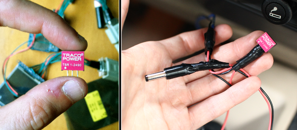
A Traco TSR 1-2490 buck convert is connected inline with the power connector to supply a clean 9 volts.
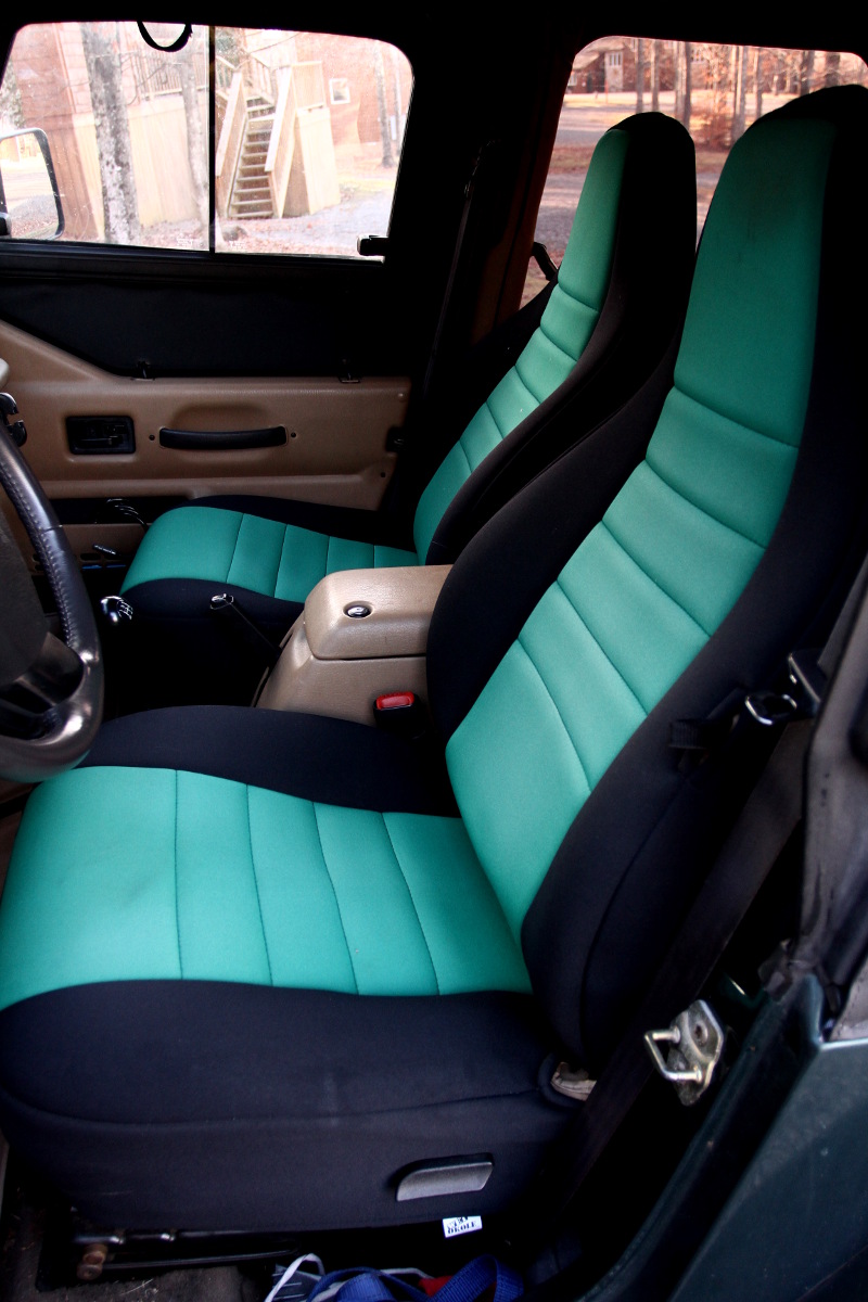
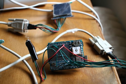
Since I haven’t finalized the installation, the cockpit of the car is a mess of wires that I can connect to the microcontroller when I put it into the car.
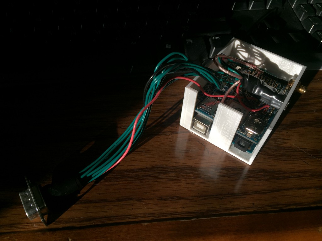
And the controller itself is sort of a mess (but somewhat less delicate that you’d think — yay for solid solder joints!).
But hey, it works! So the next step is to make some custom enclosures, and tidy everything up. I have some ideas, but I might not get around to it for a few months.