Once you own a car with seat heaters, it’s hard to go back. The old VW had heated seats; the new Jeep did not. Clearly, this state of affairs could not stand.
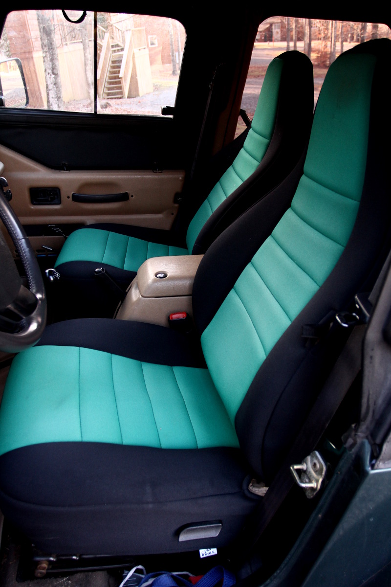
I found that I could get some nice, neoprene seat covers with built-in seat heaters made by Wet Okole. The Wet Okoles came with heating elements in both the butt-area and the back-area, whereas some aftermarket heaters only heat the butt. I used Quadratec’s “designer” for Wet Okoles. When the seat covers arrived, I installed them, and there was much rejoicing.
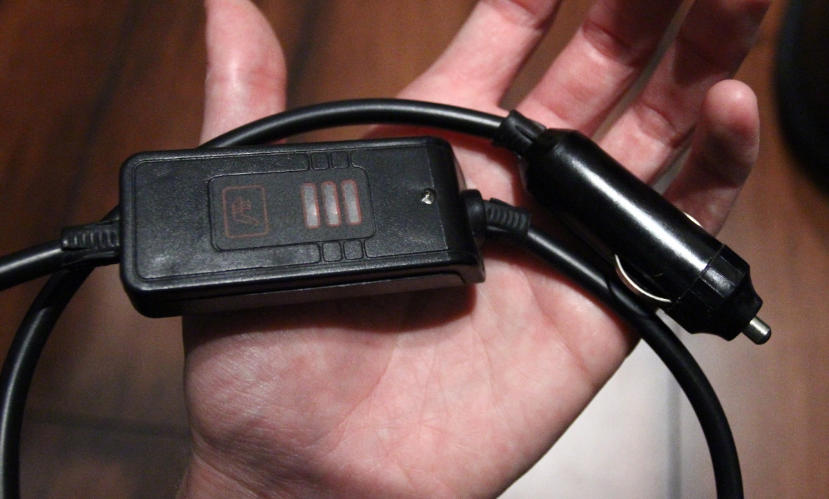
Each seat had a cigarette lighter plug for power, and a push-button switch that allowed setting the heater element to Off, Low, Medium, or High.
Here we get to the problem: While convenient for a quick connection, I didn’t want wires dangling from the seats to the cigarette lighter. Further, I only had one cigarette lighter. Even splitting the circuit for the cigarette lighter wasn’t a great solution, as each seat could potentially draw a little more than 10 amps, and the lighter was on a 20 amp fuse. Splitting the circuit would mean that I’d risk blowing the fuse each time both seats were on full. The Jeep conveniently has a spare 20 amp circuit on the fuse block behind the dash, but it’s an unswitched circuit. If I used that, it’d only be a matter of time before I’d leave the car with a seat heater on, and I’d come back to a dead battery.
After using the seat heaters for a while, I decided that they were keepers, so it was worth investing in a more permanent solution to the power problem — and a solution that would allow both seats to be heated at the same time. I needed to add at least two new 15 or 20 amp, switched circuits to the car, and I wanted controls that were integrated into the dashboard somehow.
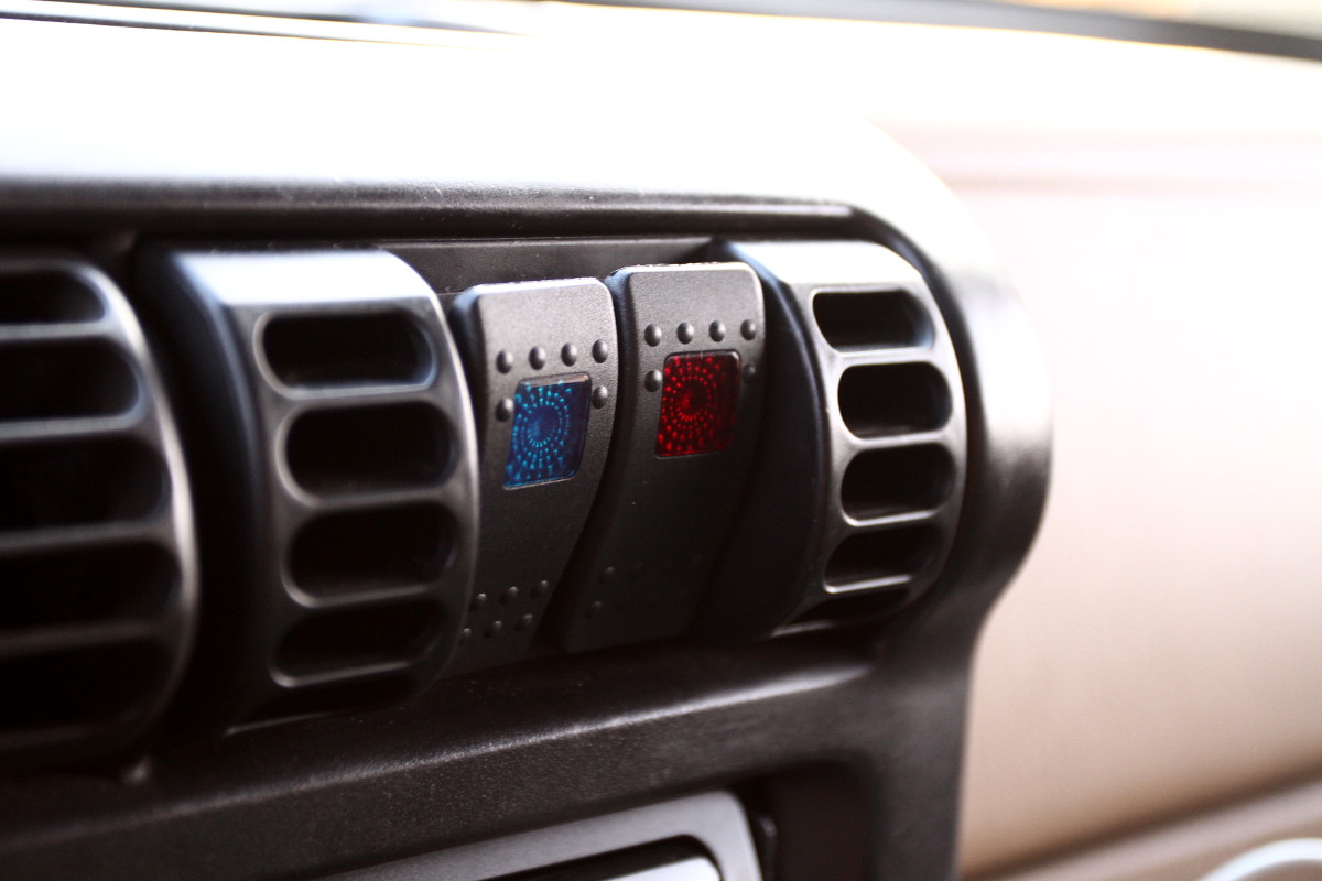
For the controls, I started looking around for switches that could put into some existing blanks on the dash. However, after bashing in a heater vent (by transporting some furniture in the passenger seat), I stumbled upon the perfect solution in a Daystar replacement vent with an integrated switch panel.
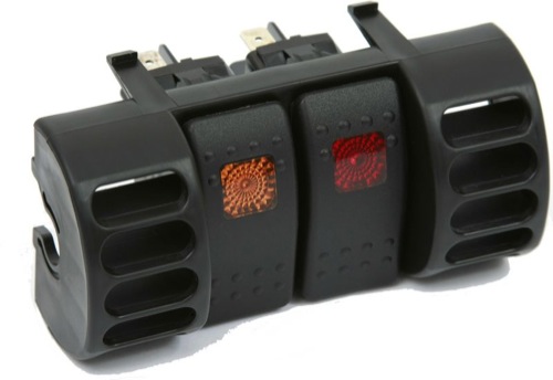
The drawback of the rocker switches is that I would no longer have Low or Medium settings. The seat heaters would either be off, or fully on. But really, who need a “lightly warmed” bum in winter? If it’s cold enough to turn ’em on, turn ’em on ALL THE WAY, I say!
For the circuits, I found that Painless Performance makes three- and seven-circuit add-on fuse blocks. I decided to go with the seven-circuit block to give me room for expansion in future, yet-to-be-conceived projects (such as my Arduino-based trip computer). That gave me four new switched circuits, and three new constant circuits, all at 20 amps.
The parts arrived, and so I got to connecting all the pieces. The trickiest decision was where to mount the new fuse block. I had initially intended to mount it behind the glove compartment, next to the existing internal fuse block, but there wasn’t enough room. Perhaps I could have found another spot behind the dash, but I didn’t want to put it somewhere that would require ripping open the dash to access it (in case I should need to replace a fuse). There was an empty spot in the engine compartment (for a second battery, I suppose, to power a winch that I’m unlikely to add) that seemed like a good candidate. Being in the engine compartment, I wanted to add a bit of protection to the block, as it wasn’t marketed as a weatherproof component. So rather than mounting it directly, I mounted it to the inside of a small tupperware bin. I drilled a few ventilation holes in the bin, and a larger hole to run the wires, then mounted the bin in the engine compartment.
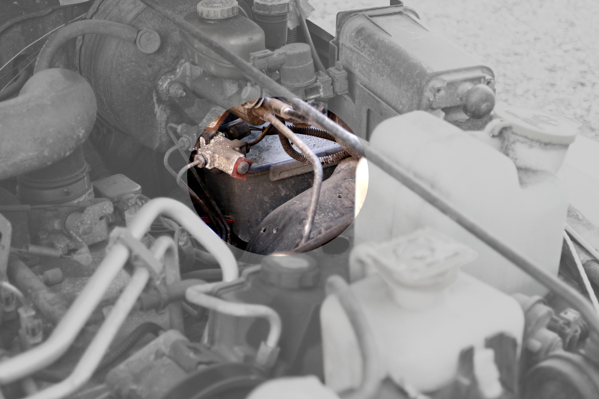
The new fuse block is in a ventilated tupperware bin, mounted near the back-driver-side of the engine compartment.
The fuse block had three sets of wires:
- Two wires to connect to the positive and negative poles of the battery to power the circuits.
- A single wire that needed to be connected to an existing switched circuit. This wire poweres an internal relay that controlled the switching of the four switched circuits in the fuse block.
- Seven hot wires for the seven new circuits.
Since the fuse block was already in the engine compartment, running the first set of wires to the battery was fairly trivial. The rest of the wires, though, had to make it into the cabin, which meant getting them through the firewall. I spent more than a few minutes looking for an accessible, existing run through the firewall, and was met with no success. I refered to Dr. Google, and learned that a hard, rubber plug near the gas pedal is the preferred channel — just make a hole straight through it. I made the hole, and pulled the wires through.
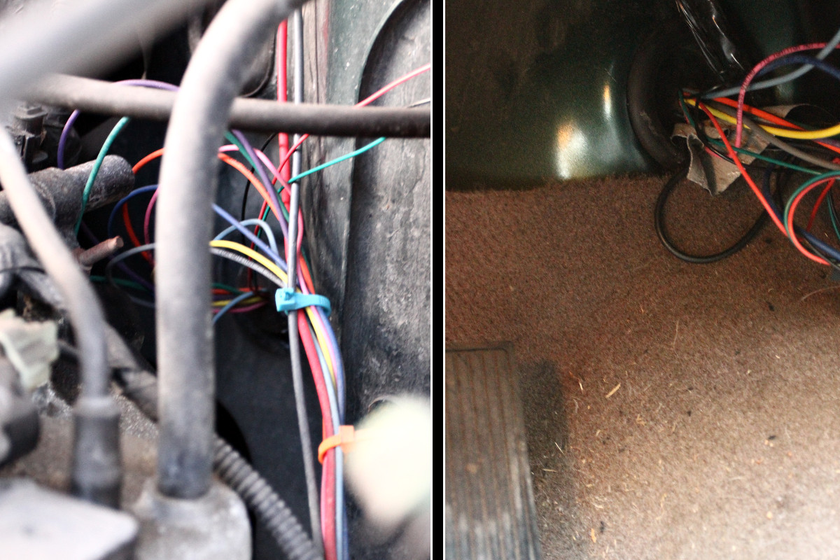
To get the wires through the firewall, I had to make a hole in a rubber plug that seemed to exist for exactly that purpose.
For the relay wire, I tapped into the hot line for the cigarette lighter — I just cut away a centimeter of insulation, joined the relay wire, and wrapped it up neat and tidy with electrical tape. The remainder of the work consisted of running wires up and down behind the dash: hot circuit wires to switches, switches to positive wires for the seats, switches to ground, seats to ground.
As of this blog post, the seats have been keeping my bum warm for more than two winters. A boy could hardly ask for more.